Draw a Machinery process(绘制机械流程(Machinery process))
To create a model of a process using the Machinery application, you can derive a process model automatically from historical observations by process mining, or you can define a process manually by drawing states and transitions.
You may want to use the manual process drawing tools in situations when you have a physical process in mind that you want to model and visualize graphically, or when you need to modify and enhance an existing process model.
From the blank canvas of a Machinery resource, your first step in manual process drawing is to create a process container. The container is used to represent a specific type of entity and its states; for instance, a Claim. If there are multiple entities interacting with each other, you may add further process containers, either in parallel or nested within others.
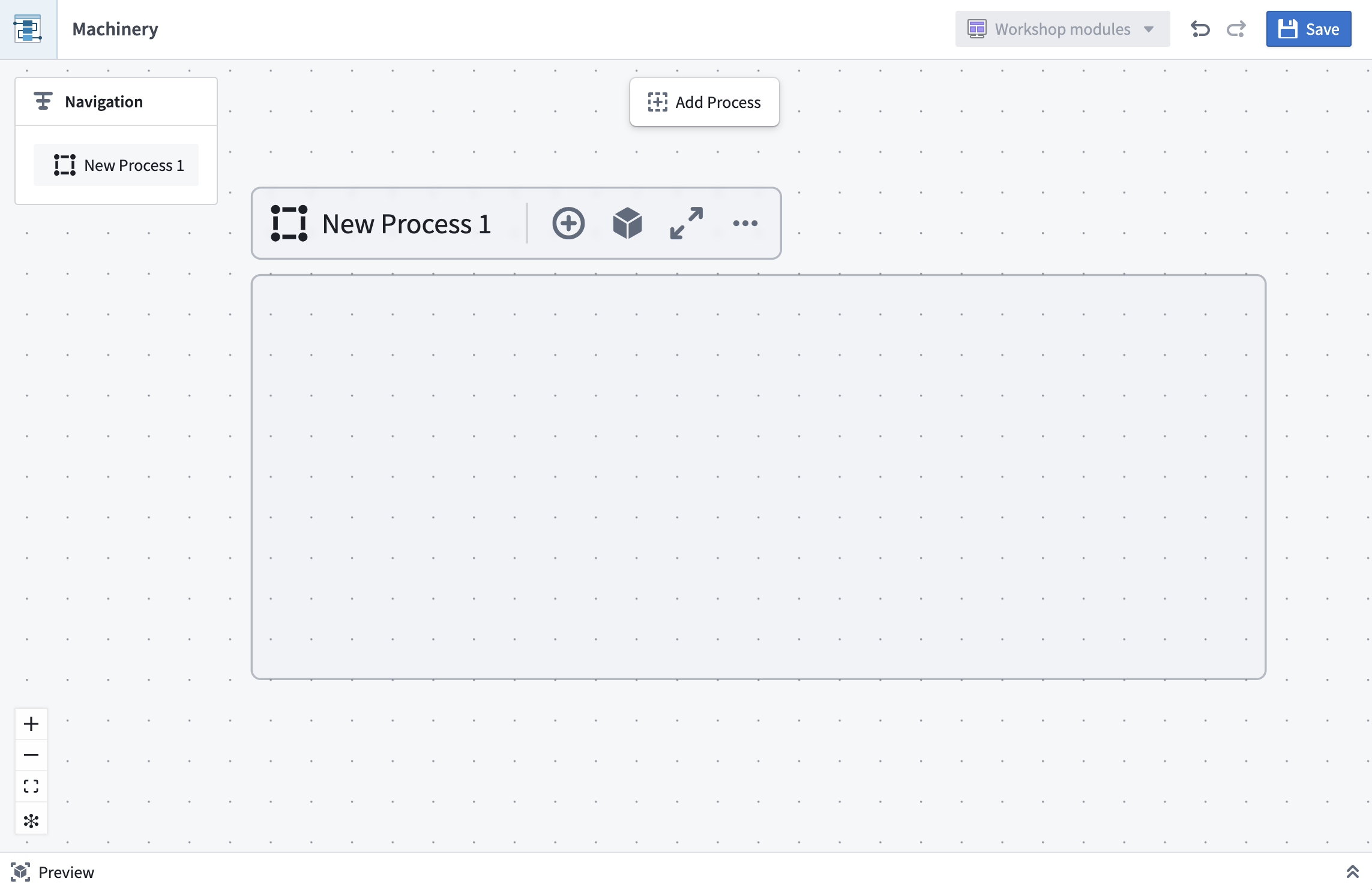
For a better editing experience, you can focus your view on a process container by selecting the fullscreen option to have the process container and its children fill the entire canvas. To revert from fullscreen focus, you can change your view by using the Navigation panel.
All drawing interactions are available through actions on the process container, or from the main toolbar when a process is in focus.
Adding states, actions, and automations
A typical pattern for building out a process is to start with an initial state, draw subsequent states, and then add actions and automations in between.

Alternatively, you can start with a sequence of actions and fill in the states later.
Edges between states denote state transitions. When connecting actions or automations to states, these edges follow the semantics below:
-
Input States: Allowed states of objects prior to the action. For Foundry actions, this can be enforced through submission criteria. You can inspect existing submission criteria in the Details panel of action nodes.
-
Output States: Possible resulting states after the action. For instance, an action to extract entities can result in extraction succeeded or extraction failed. Output states cannot be enforced; however, output states can be manually validated by reviewing the action logic in Machinery.
-
Automations: A representation of an action that is automatically triggered when one of its input states is reached. Automations can also send notifications, which describe a side effect of a state.
Nodes and edges can be deleted by selecting the element and using the trash can icon or pressing backspace on your keyboard.
Once you have chosen a process ontology, the state names represent values of the state property of your object types. Changing the name of a state in Machinery does not change values in your data. You can also link concrete actions or automations to the elements on the graph. In doing so, you can gradually turn your process model into a process implementation.
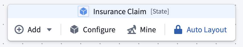
Auto-layout feature
Machinery’s auto-layout feature is enabled by default. Nodes are automatically positioned as you add or connect them, keeping the graph organized in a left-to-right process flow.

You can influence the vertical ordering of nodes of the same “layer” by dragging them up or down.
If there are loops in your process, you can choose which nodes to place first by dragging any node leftward. The rest of the layout will adapt accordingly.
You may also choose to toggle off the auto-layout feature if it does not produce satisfactory results. Switching off the feature allows you to move nodes freely on the graph.
During manual layout mode, you may benefit from the one-time layout option accessible in the control bar on the bottom left to reorganize your graph.
Multiple object types
Many real-world processes involve multiple entities. You can represent those with process containers and link their states and actions. For instance, an action in one container may affect the state of another entity and therefore be connected to those states as outputs. We recommend placing actions into the container of the object that they take as input.
中文翻译
绘制机械流程(Machinery process)
要使用机械应用(Machinery application)创建流程模型,您可以通过流程挖掘(process mining)从历史观测数据中自动推导流程模型,也可以手动绘制状态(states)和转换(transitions)来定义流程。
在以下场景中,您可能需要使用手动流程绘制工具:当您心中有一个物理流程需要建模并以图形方式可视化时,或者当您需要修改和增强现有流程模型时。
从机械资源(Machinery resource)的空白画布开始,手动绘制流程的第一步是创建流程容器(process container)。该容器用于表示特定类型的实体及其状态,例如一个Claim(索赔)。如果有多个实体相互交互,您可以添加更多流程容器,这些容器可以并行排列或嵌套在其他容器中。
为了获得更好的编辑体验,您可以选择全屏选项,将视图聚焦于某个流程容器,使其及其子容器填满整个画布。要退出全屏聚焦,您可以使用导航(Navigation)面板更改视图。
所有绘制交互均可通过流程容器上的操作实现,或者在流程处于聚焦状态时通过主工具栏实现。
添加状态、操作和自动化(Adding states, actions, and automations)
构建流程的典型模式是从初始状态(initial state)开始,绘制后续状态,然后在它们之间添加操作和自动化。
或者,您也可以从一系列操作开始,稍后再填充状态。
状态之间的连线表示状态转换。当将操作或自动化连接到状态时,这些连线遵循以下语义:
-
输入状态(Input States): 操作之前对象的允许状态。对于Foundry操作,这可以通过提交条件(submission criteria)来强制执行。您可以在操作节点的详情(Details)面板中检查现有的提交条件。
-
输出状态(Output States): 操作后可能产生的状态。例如,一个提取实体的操作可能导致提取成功或提取失败。输出状态无法强制执行;但可以通过在机械应用中审查操作逻辑来手动验证输出状态。
-
自动化(Automations): 当达到其输入状态之一时自动触发的操作表示。自动化还可以发送通知,描述状态的副作用(side effect)。
节点和连线可以通过选中元素后使用垃圾桶图标或按键盘上的退格键来删除。
一旦您选择了流程本体(process ontology),状态名称即表示对象类型中state属性的值。在机械应用中更改状态名称不会更改数据中的值。您还可以将具体的操作或自动化链接到图中的元素。通过这种方式,您可以逐步将流程模型转化为流程实现。
自动布局功能(Auto-layout feature)
机械应用的自动布局(auto-layout)功能默认启用。当您添加或连接节点时,节点会自动定位,使图形保持从左到右的流程组织。
您可以通过上下拖动节点来影响同一“层”中节点的垂直顺序。
如果流程中存在循环,您可以通过向左拖动任意节点来选择优先放置哪些节点。其余布局将相应调整。
如果自动布局功能未能产生满意结果,您也可以选择关闭该功能。关闭后,您可以自由移动图中的节点。
在手动布局模式下,您可以使用左下角控制栏中的一次性布局选项来重新组织图形,这可能会对您有所帮助。
多种对象类型(Multiple object types)
许多现实世界的流程涉及多个实体。您可以使用流程容器来表示这些实体,并链接它们的状态和操作。例如,一个容器中的操作可能会影响另一个实体的状态,因此需要将这些状态作为输出连接到该操作。我们建议将操作放入其输入对象所在的容器中。